
Cludforma Series
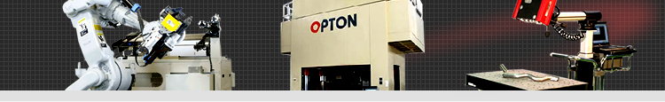
Robotic pipe bender that substitutes human operator with remarkable efficiency achieved by 「10% enhanced productivity 」 and 「prototyping and replenishing production as short as in one-tenth only needed」
Product outline
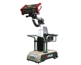
Performance for prototype bending of a medium- or smaller-sized work piece. The machine executes profiling by the camera that is manually travelled to the best positioning to the work piece.
【PT-1】
By interfacing the profiler to the pipe bender, one-time profiling will find dimensional error on a bent specimen, which is further followed by automatic creation of compensation data for immediate quality production to start. Attached parts and branched pipe can also be profiled.
【GP-1】
Same function is implemented in the machine of this type as the type PT-1 with additional function of 3D profiling on a press-molding of 50cm or less each size and compensational verification of the profiled data to those of CAD.
【Quality bending in collaboration of Opton bender and Cloudforma】
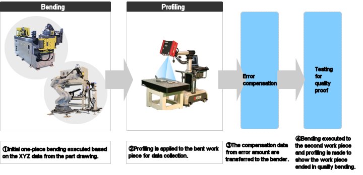
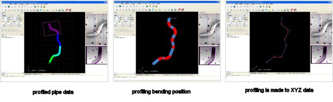
Profiling in image
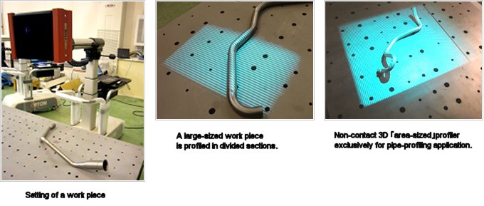
Non-contact 3D 「area-sized」 profiler exclusively for pipe-profiling application
In the pipe bending business, a skilled operator must have been involved in adjusting the best bending data over spring back and resulted elongation etc. that are affected by varied behaviors in material qualities among parts. An inspection gauge is also a "must" to test the shape achieved in mass-, and/or replenishing-production at extra cares for the storage. For prototyping work the testing gauge must always be kept with frequent modifications whenever to meet design changes.
Gauge-less production can be made by setting in a production line a non-contact 3D profiler 「Cloudforma」 ( typePT-1 and GP-1available) which is powered by the profiler's function of comparison between CAD data via the data measured on a bent work piece, automatic feed back of the error-compensation data to the bender, and digital inspection as well.
Profiling in image (Type PT-1, GP-1)
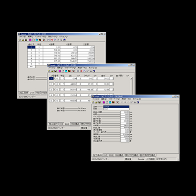
Exampled reports upon profiling of a work piece (Type PT-1、GP-1)
- (1)Basic data of work piece:
- OD:41.3mm Number of bending points 6 Bending radius 45.0mm
- (2)Bending points in coordination distance(mm)
-
Point No. X Y Z 00 608.514 240.070 21.609 01 519.051 320.815 70.595 02 402.824 301.025 63.778 03 323.836 450.106 40.718 04 335.361 545.488 16.351 05 266.847 659.079 38.800 06 73.084 749.347 17.864 07 355.766 857.512 24.133
- (3)PRB Data
- Offset Distance 105.878mm End of Length 83.873mm
-
Process No. DBB(mm) POB(deg) DOB(deg) 01-0: 0 0 56.558 02-0: 61.504 143.541 71.481 03-0: 123.826 14.687 34.729 04-0: 66.599 156.759 44.582 05-0: 76.69 158.252 82.411 06-0: 75.72 177.92 59.747
- (4)Work piece length:
- 667.173(mm) Dx=252.749 Dy=-617.440 Dz=-2.523
Shape profiling in image (Type GE-1,GP-1)
Features
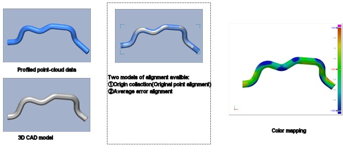
- Error verification by data comparison between center-line profiling data and CAD data (Refer the table above for Type PT-1 and GP-1)
- The amount of error are automatically compensated and fed back to the bender. (Refer the table above for Type PT-1 and GP-1)
- Profiling is repeated for revised data on a work piece whose shape produced might have been mutated due to an inconsistent installation of resetting tools. The collected bending data are processed for error compensation to meet new quality production. (Refer the table above for Type PT-1 and GP-1)
- Profiling is also applied alongside of designated dimensional distances of end-formed area as well as installation position and direction of mounting parts. (Refer the table above for Type PT-1 and GP-1)
- Profiling is also made on the designated points to find interrelated dimension of assembled work pieces like air-controller pipes and/or exhaust manifold pipes. (Refer the table above for Type PT-1 and GP-1)
- Profiling is made to find the inner and outer R-lines for establishing of the mean center R-line over bent sections. (Refer the table above for Type PT-1 and GP-1)
- Profiling is made over the free and full shape of single part including flanges, pressed metals and die-casted parts. (Refer the table above for Type PT-1 and GP-1)
- 3D CAD drawing cab be made from the profiled data on a master work piece and/or master fitting parts. ( Type PT-1 and GP-1 plus Redesigning software XOR)
Series
| Type | 3D Camera Specification | Function | |
|---|---|---|---|
| GE-1 | General Application Type | ●Nos. of pixcels 1.4 milion pixcels 5milion pixcels(for high density type) ●Per-shot field of view 300×250×300 |
●Profiling over full shape of free designed parts including press-mold, die-casted parts and mold dies |
| PT-1 | Pipe application specialty | ●Nos. of pixcels 1.4 milion pixcels 5milion pixcels(for high density type) ●Per-shot field of view 300×250×300 |
●Exclusively for pipe bending application ・Comparative verification the error correction of the data between drawing and profiled. Gauge-less Digital testing can be met. ・Automatic processing of spring back and elongation from profiled data. |
| GP-1 | General + pipe application type | ●Nos. of pixcels 1.4 milion pixcels 5milion pixcels(for high density type) ●Per-shot field of view 300×250×300 |
●Applicable to either profiling of 3D surface and/or bent work pieces. |

 Bend-Master (BEM)
Supporting Software for Bending Bendmaster (BEM)
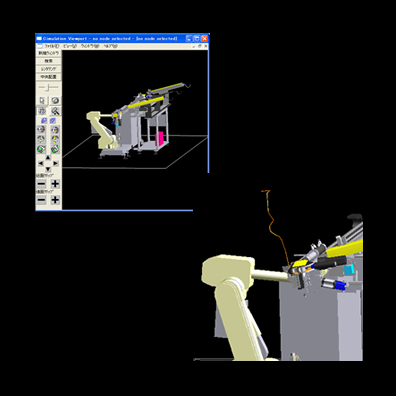 Bend simulation software
 3D profiler for pipe
3D Profiler for Pipe
Inquiry and/or consulation
 Contacts are most welcome to Opton/MiiC sales group at following telephone number.
America:+1-734-453-2188
Mexico:+52-55-5203-3027
German:+49-89-540165-12
Japan:+81-561-48-3382
Sales affiliates of Opton group
 We have sales locations in USA, exico,Germany and HQ in Japan.
Opton , as pipe bending machine specialty with rich and market-oriented know-how, can assure people in manufacturing markets for enhanced production performance by our products of profiling machinery.